HAAS UMC750 with Angled Head
Setting up the tools and post properties to use the Angled head
Tool creation:
In order for the post to calculate the tool position correctly, It needs the distance from the center of rotation of the spindle to the face of the tool. To do this, Create a holder that represents the angled head and apply that to the tool.
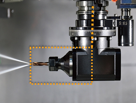
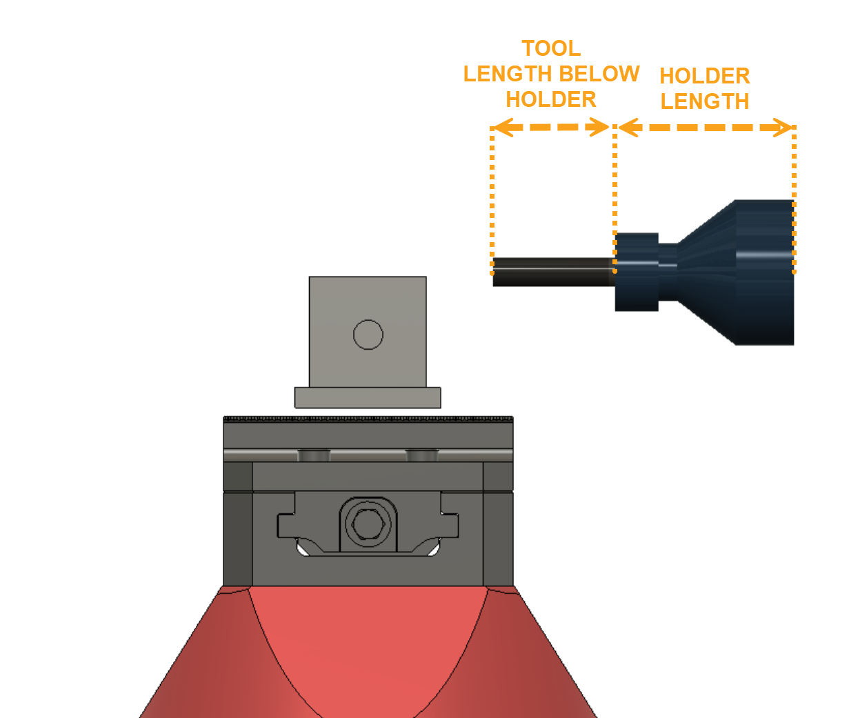
Holder setup:
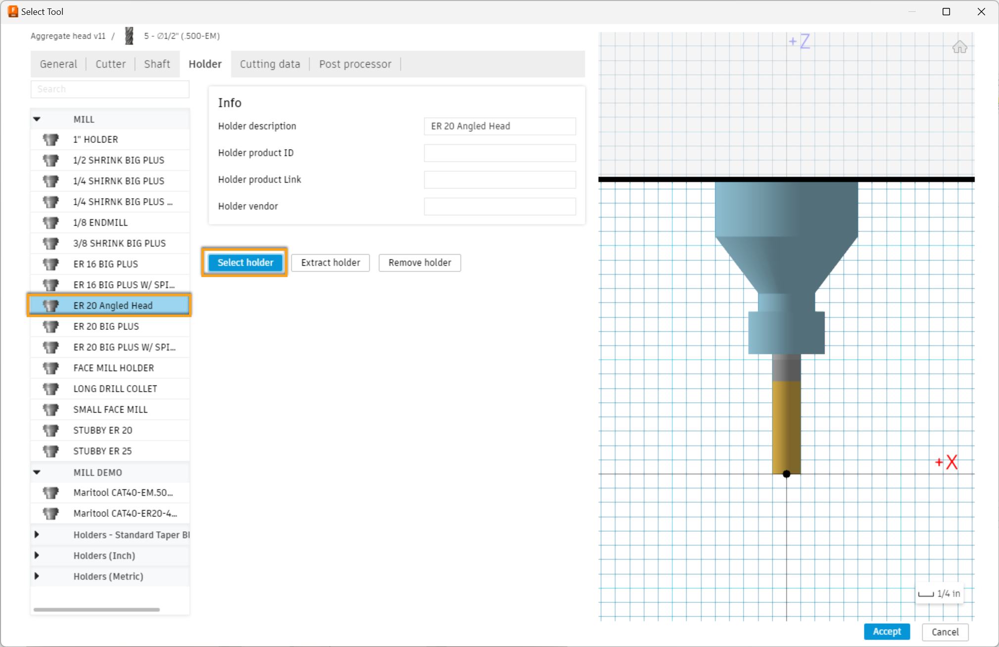
- Create a new tool holder to represent the partial angled head
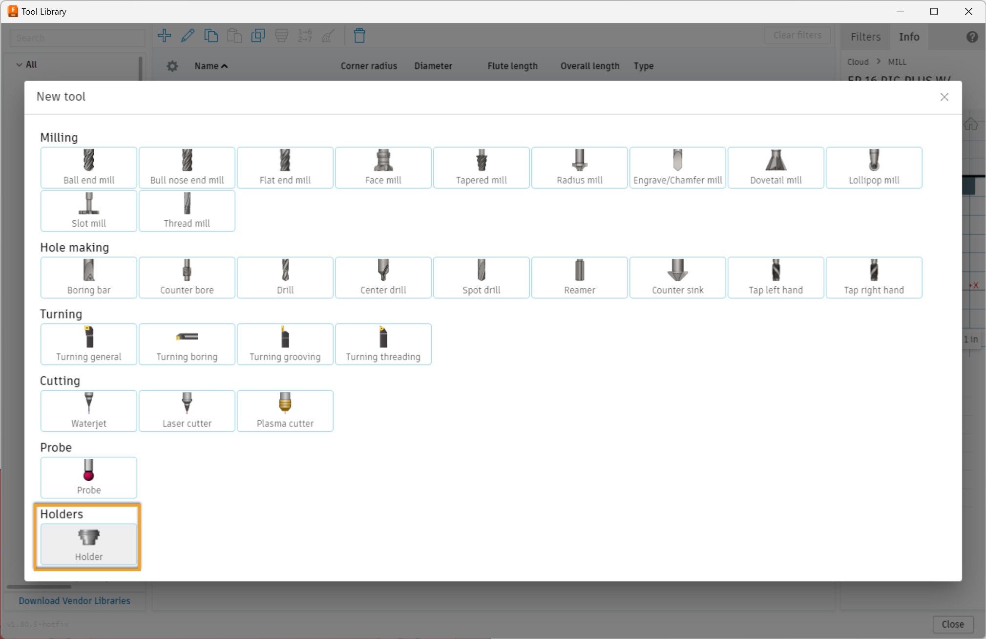
- Model with the overall length being as accurate as possible since this is used in the calculation in the post
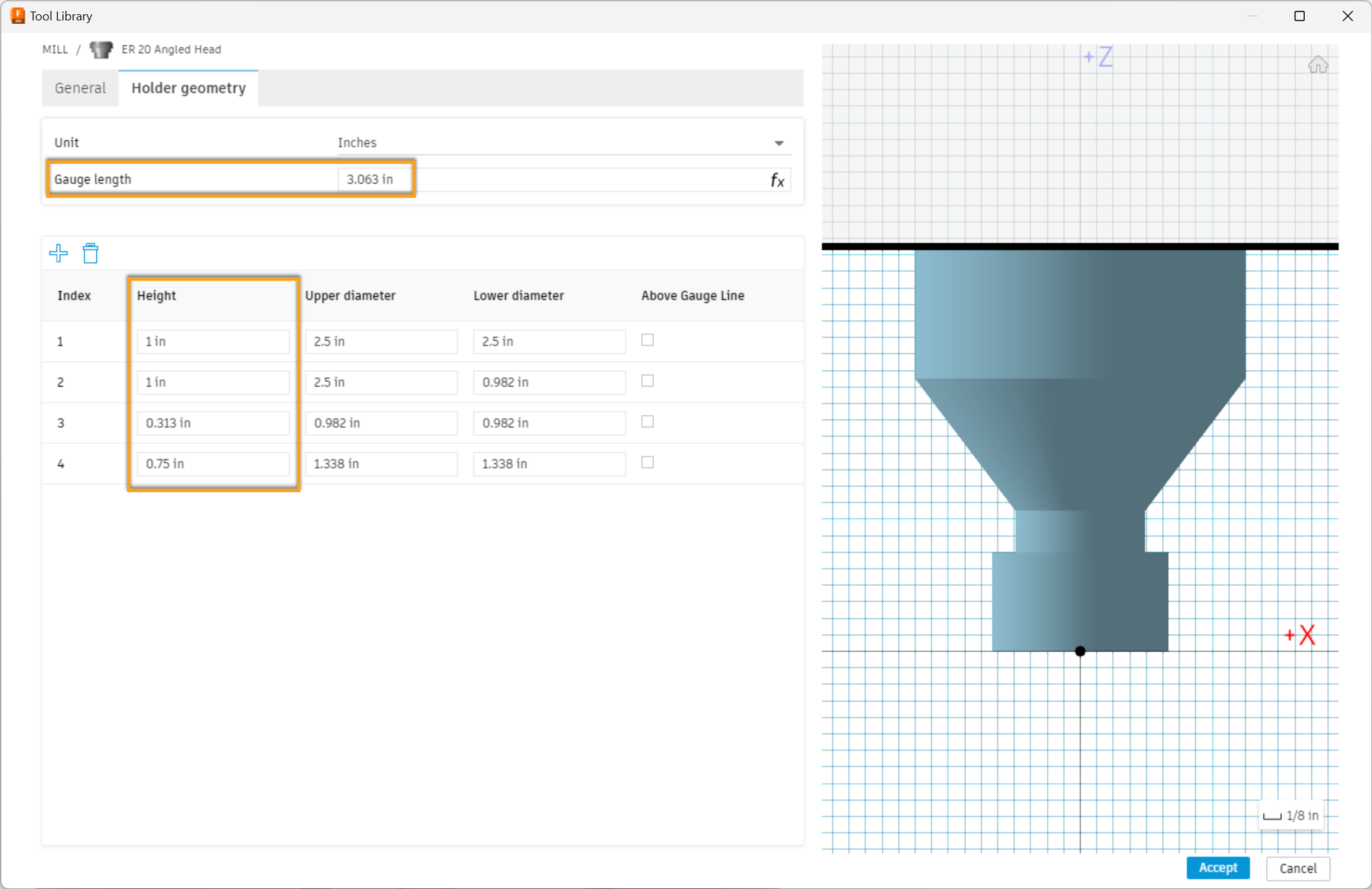
Tool setup:
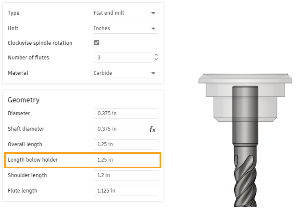
- Create your tool with the Length below holder equal to the stick out from the tool holder
- Attach the newly made angled head holder to the tool
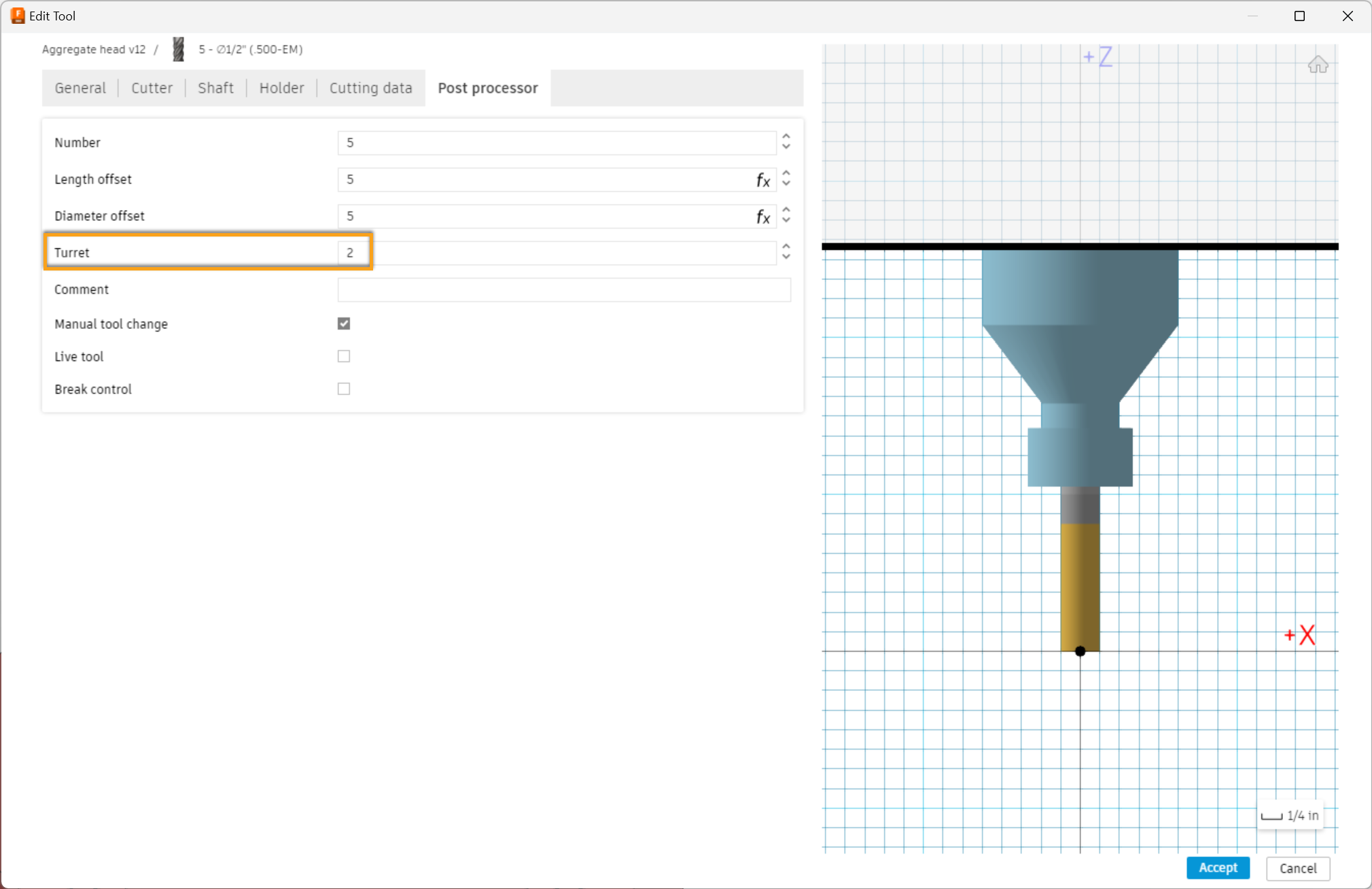
- Change the tool turret value to 2, This tells the post to switch to using the angled head position logic instead of the normal 3+2
Post Properties for the Angled Head:
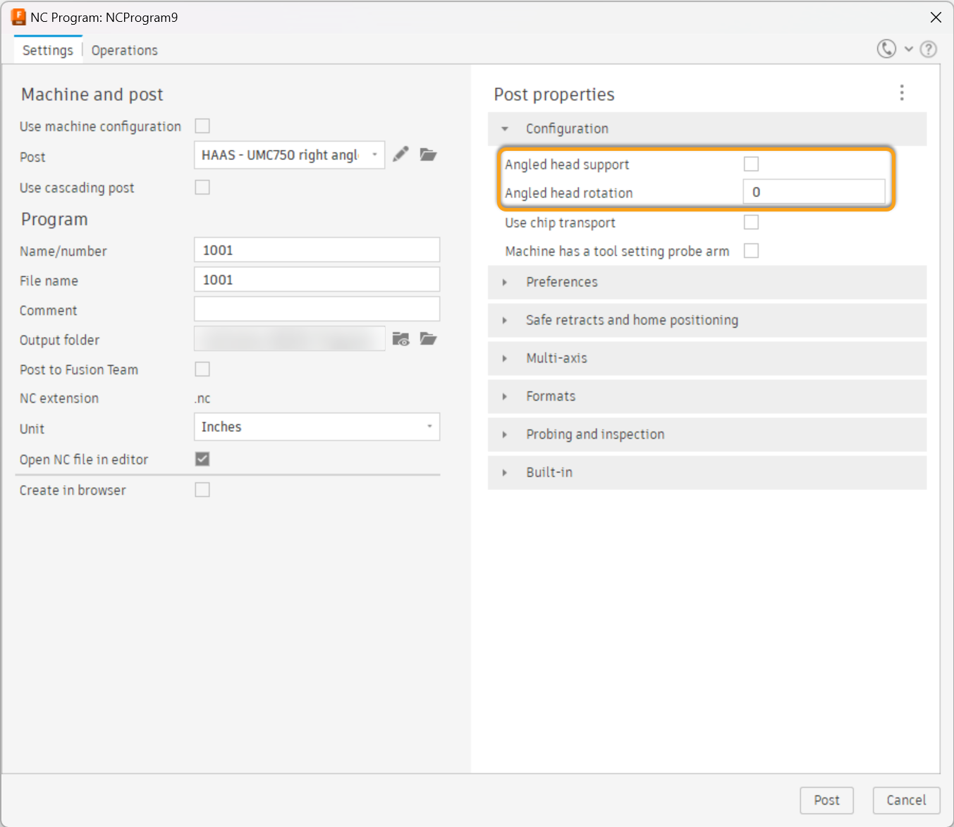
- Angled head support turns on the logic for the Angled head
- Angled head rotation is the M19 R# value to lock the spindle. this value is then added to the C-axis position for the toolpath
Usage:
Use the Z tool orientation to choose the desired cutting position and the post will calculate the offset position based on the tool and holder lengths.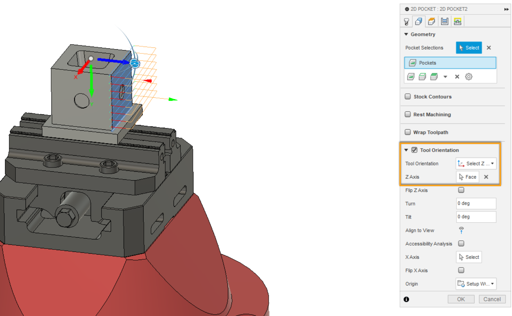
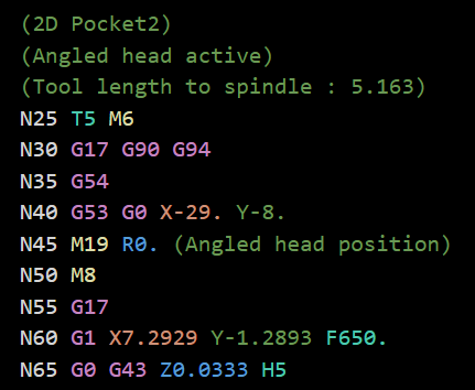
If setup correctly, The post will output the tool length from the spindle (tool below holder length + holder length) And comment that the angled head is active
![DSI-small-square.png]](https://know.dsi-mfg.com/hs-fs/hubfs/Logos/DSI%20Logos/DSI-small-square.png?height=50&name=DSI-small-square.png)