![DSI-small-square.png]](https://know.dsi-mfg.com/hs-fs/hubfs/Logos/DSI%20Logos/DSI-small-square.png?height=50&name=DSI-small-square.png)
Issue
The robot is not moving where I expected it to.
Answer
How robots are defined from the factory
- A robot is typically shipped or initially set up with a Tool Definition at the end of its 6th axis or robot flange. It is typical for this coordinate system to be defined with the positive Z direction pointing away from the robot flange. Review the manufacturer's specifications to review how your robot is defined at the flange face.


Setting or editing a Tool Definition
- Once your end effector is attached, you will need the dimensions from the center of the flange face up to the programming point of the tool (X, Y, Z). The effective tool may be a cutting tool, knife, welder, hot wire, or gripper, to name a few.

- PowerMill and other CAM systems are traditionally made to match the Z, Y, and X-axis directions of standard CNC machine tools. This definition has the positive Z axis pointing towards the spindle and not away from the spindle. This is the required tool definition when creating toolpaths in PowerMill.
Image of a typical CNC milling machine tool definition coordinate system
- To create and execute toolpaths from PowerMill, it is required that the robot has a tool definition that has the positive Z-axis pointing in the direction of the effective tool axis. Therefore, a rotation must also be applied to the tool definition.
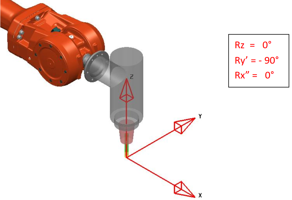
- You will now need to know if your robot uses the Euler or Quaternion convention to move and rotate the coordinate system. Also, you need to understand if you are entering degrees or radians. (You may need to convert degrees to radians.)
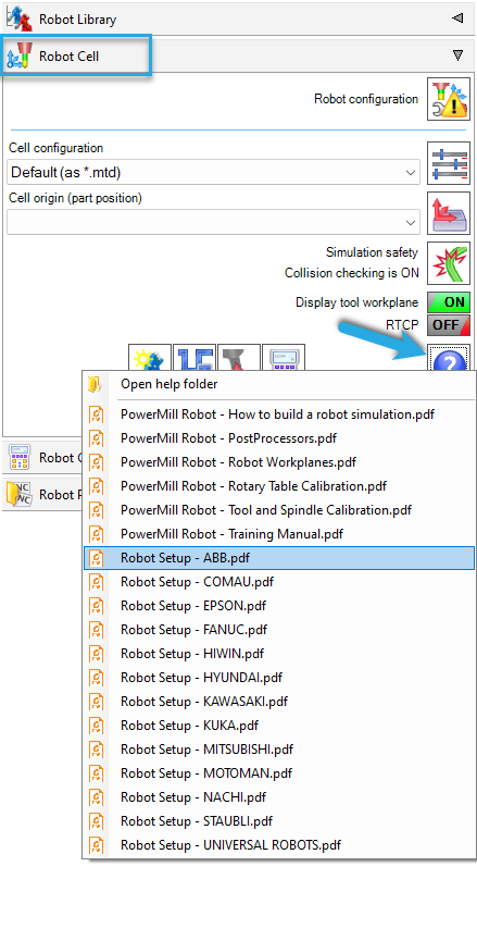
- The PowerMill Robot Interface (PRI) has some robot manufacturers defined in the PRI Help Files, but it is always best to confirm your manufacturer's specifications.
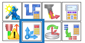
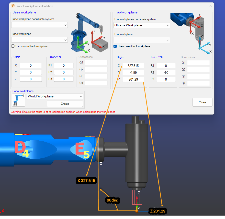
- In the PRI, the Robot Workplane Calculation utility can assist in calculating the tool definition.
- The PRI can also help you convert your rotation convention and values by using the Transformation Converter utility.

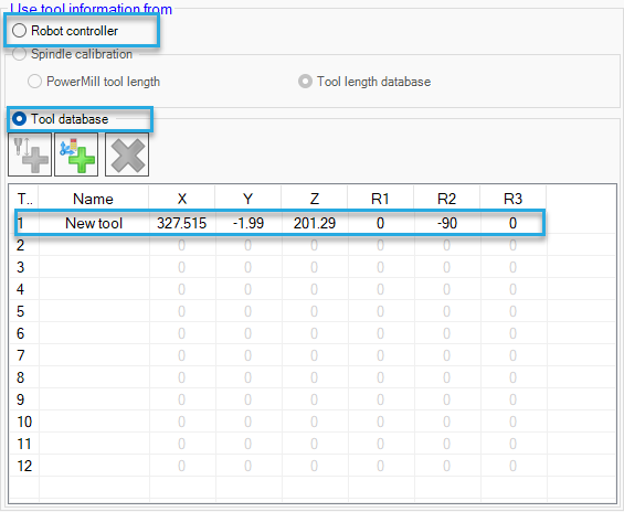
- Whether you define your tools at the robot controller or if you have your tools defined in the PRI tool database, you will need to be sure that they are correct and accurately defined for your process.