![DSI-small-square.png]](https://know.dsi-mfg.com/hs-fs/hubfs/Logos/DSI%20Logos/DSI-small-square.png?height=50&name=DSI-small-square.png)
Issue
The robot is not moving where I expected it to.
Answer
- The Zero position to locate your workpiece in a robot cell is referred to as User Frames from many Japanese-manufactured robots. ABB has a different name for these zero positions called Work Objects. Kuka also uses a different term called Base Data. Although these manufacturers call their workpiece zero positions different names, the idea is the same.
In this article, we will refer to these zero positions as User Frames.
- A robot has a programmed location commonly referred to as the Base Frame, which is not expected to be adjusted by a user. The Base Frame's location varies between manufacturers; however, it is usually located in the center of rotation for the first axis, at the bottom of the robot base, or at the intersecting centerline of axis one and axis two. It is common to program target positions that are relative to the Base Frame when programming from the robot pendant. When programming a workpiece from external software, you would typically want to "Teach" the robot where that part is located relative to the Base Frame. A User Frame is employed to shift the zero location from the robot's Base Frame to a User Frame. This shift has 6 movements that can describe the position and orientation of the workpiece. Shift along robot X, Y, and Z and a rotation Rx, Ry, Rz, using an Euler (rotary or static) convention. ABB will use a shift along the robot X, Y, and Z and a rotation Q1, Q2, Q3, and Q4 using quaternion angles.

- When setting up a User Frame, it is critical that your Tool Frame is defined correctly before teaching a User Frame. If a tool is active during the creation of a User Frame that is inaccurate, the result of the User Frame could be transposed or influenced from the tool frame definition. For more information on Tool Frame definition, visit How to properly define robot tool frames for PowerMill.
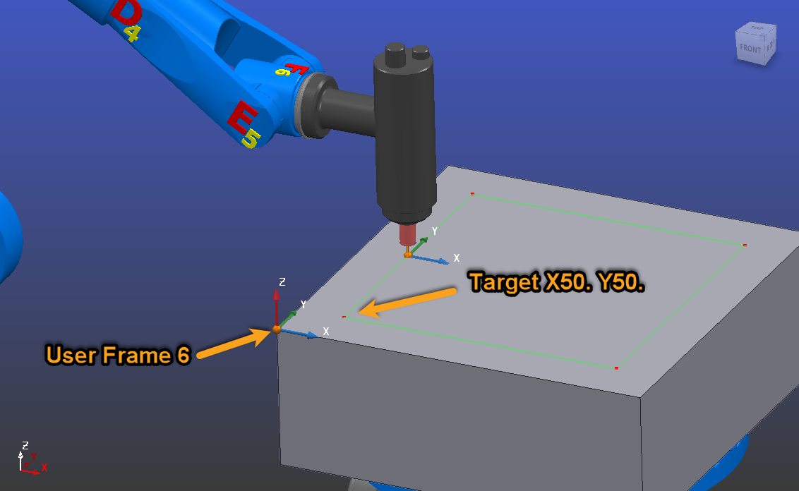
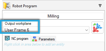
- When programming a robot from an offline CAM system, a common coordinate system must be used as a local coordinate system at the same location as the User Frame described at the robot. The robot targets will be written relative to this coordinate system so that the target locations will be output from the local coordinate system. The target location in the output robot code in the below image will read X50.0, Y50.0, Z0.0.